The force of friction is much lower than the holding (normal) force — the friction force would generally be approx. 20% of the holding force. But those are not the only forces of physics that affect magnets in production facilities and warehouses. Read more about how to make sure you use your magnetic chucks and lifting magnets safely.
Magnetic Force
You have probably experienced this: Taking two magnets apart takes some effort but sliding one to the side is pretty easy. Why is that? Various forces of physics are to blame — each force pushes the magnet in a different direction. When pulling two magnets apart vertically, the pulling force needs to be approximately 5× higher compared to sliding the same two magnets aside.
Which forces of physics affect the magnetic force of a magnetic chuck or a lifting magnet? In this article, we’ll talk mostly about the holding force, the force of friction and of course, gravity.
Holding Force = Normal ForceThe essential part of the overall magnetic force is the holding force = normal force (Fn in physics). It represents the force with which a magnet holds an object in perpendicular direction. |
Force of FrictionFriction force is perpendicular to the normal force, parallel to the magnet’s surface. It represents the force which hinders the movement to the side when two objects are stacked on each other. Its value is usually around 20% of the normal force. Which gives us the general friction coefficient — 0.2. |
Force of GravityGravitational force affects both the magnet itself and the magnetised object. We always have to consider it when working with a magnet. |
Magnetic Force of Lifting Magnets
The normal force reflects the actual load capacity of a lifting magnet. For a load to be lifted, the magnet has to surpass the force of gravity holding the load down on the ground. The relation between normal force and gravitation transcribes to safety coefficients set by legal standards (EN 13155:2020(E) standard).
|
Lifting Magnet Type |
Safety Coefficient |
|
Permanent Lifting Magnets |
3 |
|
Lifting Electromagnets |
2 |
|
Electropermanent Lifting Magnets |
3 |
All lifting magnets have to pass a so-called pull-off test (on a certified pull-off machine) before they’re released to the market. Such a test is archived and linked to the serial number of a particular magnet. Therefore, each high-quality lifting magnet should come with a load certificate with results of the pull-off test.
Lifting magnet certification is valid for a year so the pull-off test has to be repeated every 12 months. We always visit our customers to run revision tests on site with our mobile pull-off device.
Read more about the certification of our lifting magnets and how we test them before use. We apply even stricter standards for our tests than the law, to be assured our lifting magnets are 100% safe. We insert a sheet of paper between the magnet and the lifted object during tests — this simulates air capsules or surface irregularities as they often occur in practice. The actual load capacity of our lifting magnets is thus in fact higher than their stated nominal load capacity.
Lifting Objects Safely with Magnets
Inclination
Maximum load capacity of a lifting magnet is reached on condition the tilt of the lifted load is zero. The lifted object should be always centred perfectly towards the magnet.
The centre of gravity tilts every time the lifted load is not 100% centred. The force of gravity then splits in two parts:
- the normal force (perpendicular to the lifted object)
- and the force of friction (parallel with the lifted object);
while the vector sum of these two forces equals the force of gravity.
The more tilted the lifted object is, the more powerful the friction force gets. The normal force gets lower — and magnetic force as well. The highest allowed inclination is usually 6 °. This maximum tilt rule has to be abided to make sure magnetic lifting is safe.
Now, how to move around the lifted load — from horizontal to vertical position? With our NEO Lifting Magnets, we’ve solved this problem with additional equipment, such as our NEO HV Lifting Arm. It has a stop block which prevents the lifted load from sliding down. You can then use the magnetic capacity of a lifting magnet to the max.
To illustrate the difference in forces of physics caused by tilting the lifted load, have a look at our GP 250 Industrial Permanent Magnet. This magnet has no safety stop to prevent tilt and the difference in the horizontal and vertical working limit is vast (250 kg for horizontal position and 80 kg for vertical position).
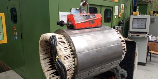
A stator packet being lifted by a magnet at Siemens facilities in Frenštát pod
Radhoštěm (Czechia). As it’s made of folded metal sheets of various structures,
we decided to perform a test-lift on site. Our NEO SPC Lifting Magnet worked perfectly.
Chemical Properties and Temperature
Magnetic force lowers remarkably in high temperatures. NEO HOT Lifting Magnets are a popular solution for using lifting magnets safely in temperatures up to 180 oC.
With regard to chemical properties, the most suitable material for magnetic lifting is standard construction steel. Elements added to alloy steel (e.g., mangane or chrome) decrease its magneticity, all the way down to non-magnetic austenitic steel.
The more homogeneous the lifted object, the better. Alloy workpieces composed of several materials and of various structures are always more unpredictable when it comes to magnetic lifting. Such as the stator packet in the picture below:
|
Tip: We always recommend testing the load capacity first when getting lifting magnets for a production where the goal is to lift objects of unusual chemical properties, shapes, lengths or objects that are not homogenous. As we did with Siemens. |
Load Dimensions and Surface
Dimensions of the lifted load (length, width, diameter) affect the overall magnetic force of a lifting magnet by far the most. That’s why the majority of lifting magnets have clearly set working limits. Most often, the length of the lifted load is limited (long and slim load bends when lifted which affects all the forces of physics at play).
The thickness of the lifted load is also important. Any dents, drilled slots or other surface irregularities can affect the maximum load capacity of a lifting magnet in a negative way.
Never underestimate the shape of the lifted load either (or, more precisely, the shape of the surface attached to the magnet). For instance, some lifting magnets cannot lift circle shaped loads.
To fulfil the potential of a lifting magnet, make sure you cover all magnetic poles when attaching the load to the magnet. Moreover, pay close attention to the diameter of the lifted load. Preferably, it should be larger than the magnetic poles. Thin workpieces always bear the risk of the magnetic field getting through and closing behind them — resulting in insufficient lifting force. Read more about handling thin workpieces in our article here >>
Last but not least, take into account possible air capsules as they almost always appear. Their causes are various — it could be non-magnetic materials on the lifted object (paintwork, foil) or just surface irregularities.
Magnetic Force of Magnetic Chucks
The science behind all the forces of physics that affect a magnet gets even more complex with magnetic chucks.
The force of gravity can affect a magnetic chuck positively (by vertical machining) or negatively (in horizontal machining).
Machining a workpiece clamped by a magnetic chuck leaves the magnet exposed to many combined cutting forces — they affect the magnet both vertically and horizontally. Cutting forces are determined by cutting conditions and the machining device’s geometry.
Different types of machining require different qualities of magnetic chucks. As a result, there are many types of magnetic chucks, each suitable for different situations.
|
Bear in mind the golden rule of magnetic clamping: A magnetic force of a magnetic chuck has to be more powerful than all the cutting forces the workpiece is subjected to during machining. It’s the only way to make sure machining operations are performed safely. |
Testing Sufficient Magnetic Force of Magnetic Chucks
The rules for testing magnetic force of magnetic chucks are not set by law (contrary to lifting magnets). Each manufacturer sets their own internal rules. Any magnetic chuck from Walmag comes with a control certificate with the values measured during performed testing.
Moreover, we always test our magnetic chucks on a certified pull-off machine while developing our prototypes.
There are several methods how to test magnetic chucks:
- JIS: Pull-off test with a test unit of 1 cm2 contact surface. The test unit is attached to a spring which is then pulled by a screw until it comes off the magnet. We measure the values of the magnetic force in kgf (kilogram-force).
- OSW: Pull-off test with a test unit of 64 cm2 contact surface. The test unit is attached to a screw which is turned around, creating tension, until the control unit comes off. This value is usually measured in lbf (poundal-force) – transferable to kgf.
How to Choose a Magnetic Chuck
Various types of machining and workpieces result in various types of magnetic chucks. These are usually made-to-measure to match requirements of a production perfectly. We always recommend considering the following factors when choosing a magnetic chuck:
The direction and angles of employed cutting forces: The optimal angle is always vertical to the magnetic pole.
Thickness of a workpiece: The thinner the workpiece, the less stable it is on a magnet (and the more magnetic field lines permeate the worktool). To clamp thin metal sheets safely, we need to adjust the density of magnetic poles — the thinner the workpiece, the denser the poles should be, in order to create a stronger magnetic field.
Learn more about clamping thin metal sheets >>
Distance of the cutting force from the magnetic chuck: The taller the workpiece, the higher the risk of it falling over. Especially when the cutting force gets too high above the magnetic surface. This risk of falling over increases when the contact surface (touchpoint with the magnet) is small.
Coverage of magnetic poles: Ideally, a workpiece should cover as many magnetic poles as possible. Make sure to cover the same number of north (N) and south (S) poles. In some cases, adjusting your machining processes might be necessary. Example: Our customer needed to cut steel rods of 2000 mm to 90 mm pieces which would then be machined. But the short 90 mm rods didn’t cling to the magnetic chuck tight enough. The possible solution would have been to set the machining device to lower power — that was a no-go for our customer. Instead, we agreed on a different approach: The steel rods get cut into 470 mm long pieces, those are machined (the magnetic force of the magnetic chuck is sufficient for the longer pieces) and only then cut to required 90 mm rods.
Coverage of the magnetic chuck: A workpiece covering only a part of a magnetic chuck’s surface is clamped by the strongest possible magnetic force (of the particular magnet). When you add another workpiece on the chuck and cover its entire surface, the magnetic force holding the original workpiece in place decreases. (With just one workpiece on the magnet, all magnetic field lines are concentrated in it. When you add another workpiece, some lines get transferred to the new workpiece — decreasing the magnetic force holding the original workpiece in place.)
Roughness of the workpiece’s surface, air capsules and compactness of a workpiece: Magnetic chucks are affected by these factors in the same way as lifting magnets. Everything that’s been said about chemical properties and temperature is also valid for magnetic chucks.
Pole extensions: They extend the magnetic field, thus adjusting the magnetic force (due to their size and other qualities). Pole extensions are:
- Fixed — e.g., single cubes or additional panels in which the negative of a sample workpiece is milled,
- Flexible — magnetised with the workpiece, securing it in the desired position.
|
Tip: Support bars or blocks also prevent a workpiece from budging. They get magnetised with a workpiece, securing it in place. Blocks are a popular fall-over prevention. |
Rules of Safe Magnetic Clamping
The overall magnetic clamping force should always be twice the cutting force. You also need to consider that tall workpieces might fall over (especially if their base is small).
|
Ft ≥ 2×G Fn×(D3 / 2) ≥ 2×G×(L / 2) |
Both these conditions have to be met. Also, please note that these equations leave out the cutting force. Should you need to consider it, split the cutting force (using the vector equation for the force of gravity) and then add the values into the equations above.
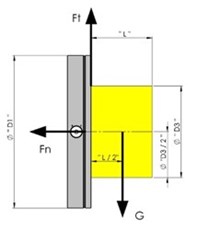
Explanatory Notes:
Fn .. the normal force (= clamping force for the workpiece)
Ft … friction force for the workpiece (Ft=kv×Ft )
kv = friction coefficient (0,15-0,3 according to the material of the workpiece, its surface, etc.)
G … Gravity (mass of the workpiece×9,81)
Don’t get scared by equations. All Walmag magnetic chucks come with a detailed user manual containing all the rules for safe clamping. And you can always get in touch with our customer support.
Considering automating your production with magnetic chucks or lifting magnets? Contact us. We’ll calculate the required magnetic force, suggest the optimal solution for you — or even lend you our magnetic chucks of lifting magnets to test them out.